
Use
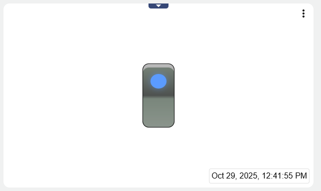
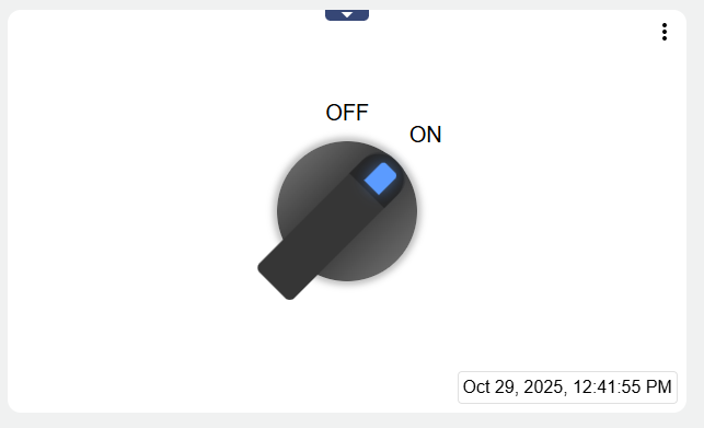
You can use the Switch to set a digital output for your signal. This can be given the value On (1 / true) or Off (0 / false).
|
Typ 1 “Switch“ |
Typ 2 “Rotary Switch“ |
|---|---|
|
|
The three dots in the upper right corner ![]()
|
|
Can be set via "Manage conditions" (see below). Allows to edit the conditions (Alarm thresholds) set in the signal. |
|---|---|
|
|
Can be set via "Include signal history" (see below). Allows you to view in list form when which historical values were stored in the system. |
|
|
Can be set via "Include signal history" (see below). Allows you to view the historical values of the signal via chart . |
Configuration
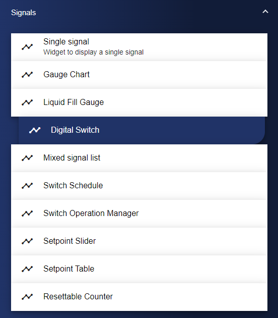
First of all, select the Switch widget from the Signals category.
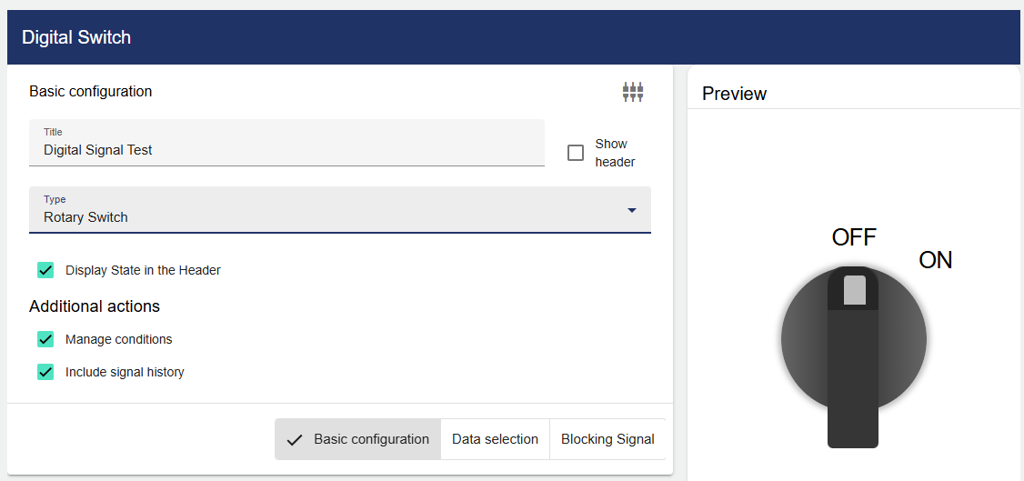
In the Basic Configuration of the Switch, assign a suitable title. The header and the value in the header can be displayed by activating the check box. Now you have to select the type of switch, you can choose between "Switch" and "Rotary Switch".
As described above, you can also set whether the conditions and signal history should be displayed.
Then go to the "Data Selection" tab and click "Signal".
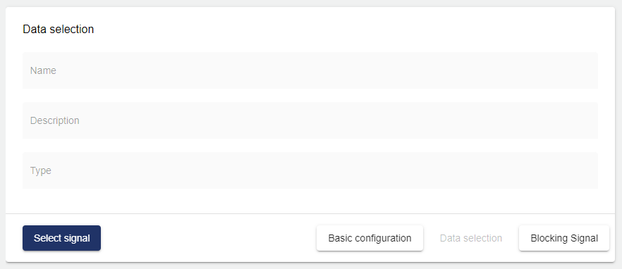
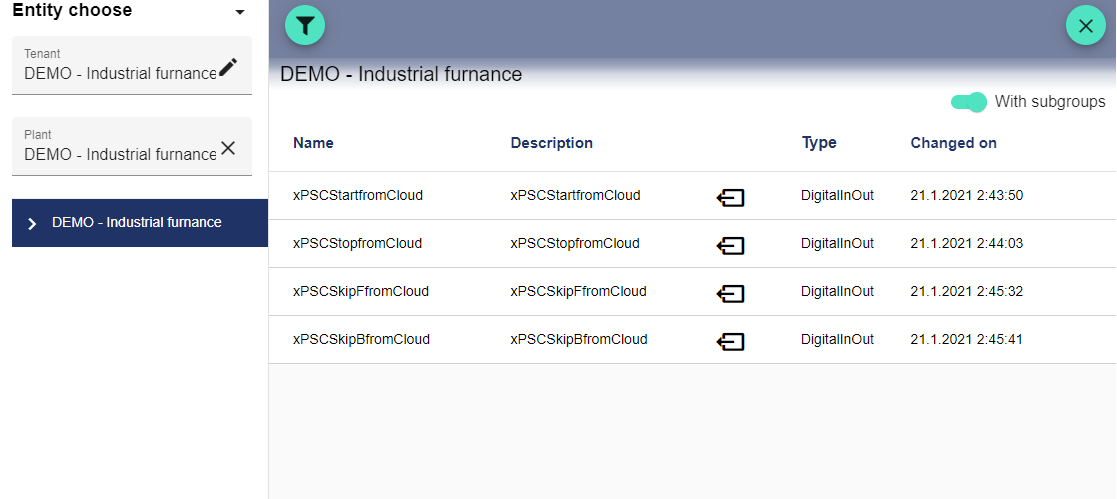
Clicking "Select Signal" opens the Select Entity window. You can add a previously created signal here.
With the "Lock signal" it is possible to prevent the digital signal from being changed in this widget. The "Data Selection" signal is locked when the "Lock signal" is active.
Once you are satisfied with your configuration, you can save it.