General information
This block is only required if the JUMO Modbus devices used have a calibration function. Otherwise, this step can be skipped.
This block ensures that the sensor that is in calibration mode receives exclusive access to the interface; communication with all other sensors is prevented during this time. The sensor in calibration mode therefore has priority over all other participants. However, other sensors are activated alternately and each in quick succession so that their measured values can still be updated during the calibration phase.
Adding the digiLineBasic library to the Library Manager is essential to ensure seamless functionality.
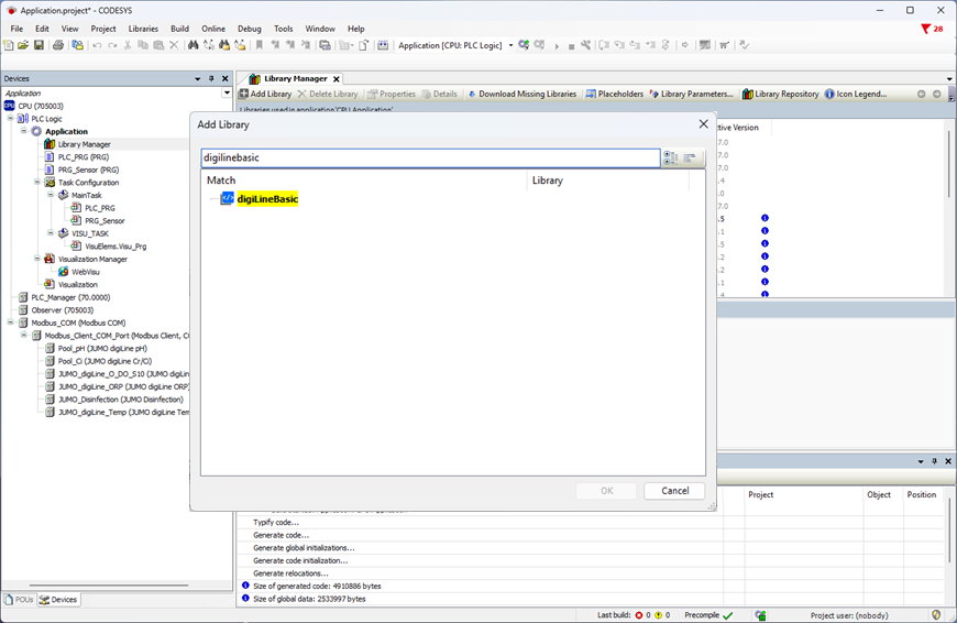
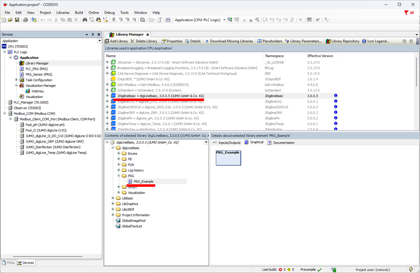
If two or more sensors are connected to the interface, the FB_ComPortControl block is required. In the JDigilineBasic library, there is an example file PRG_Example which can be opened by double-clicking.
The rows can be copied and pasted into your own "Program".
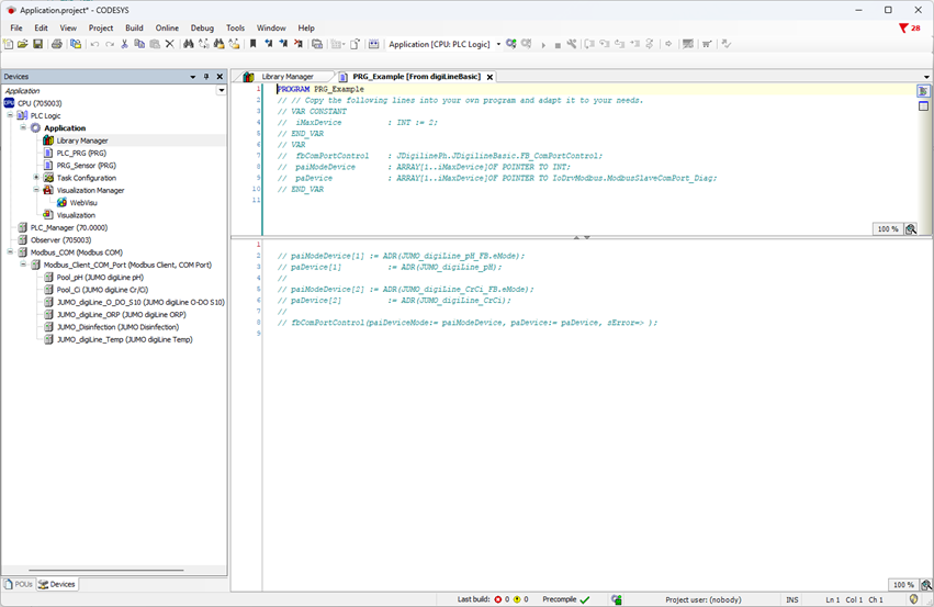
A 2 must be input for iMaxDevice as two sensors are connected to the interface in this example.
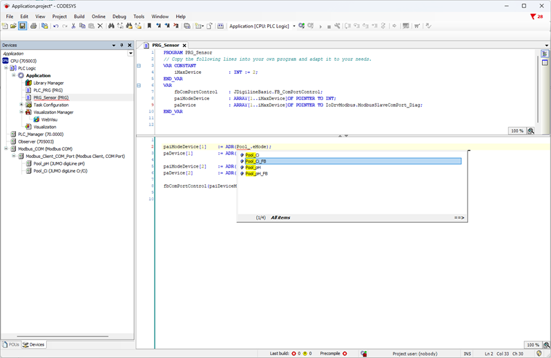
Enter the sensor name with the suffix "_FB" for paiModeDevice. Only enter the sensor name for paDevice.
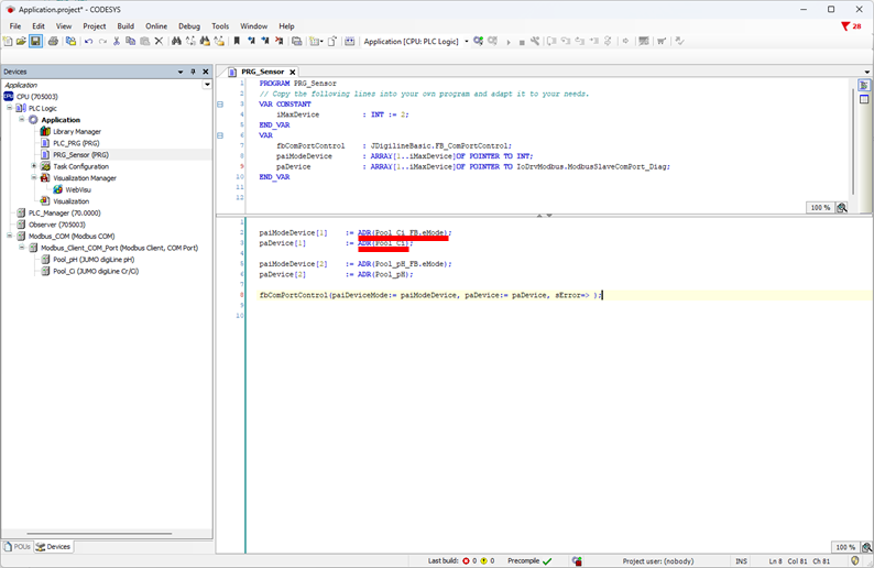
Connecting an external/your own sensor to FB_ComPortControl
If an external sensor (or a sensor driver you have developed yourself) is connected to the interface, it must also be controlled using FB_ComPortControl when a JUMO Modbus device switches to the calibration state.
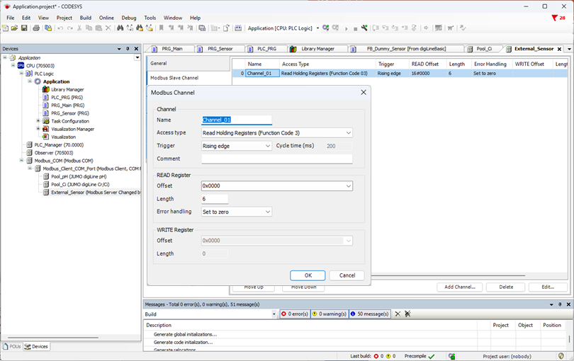
Caution: If you want to connect an external/your own sensor, the trigger must also be "Rising edge". CODESYS has problems with different trigger types.
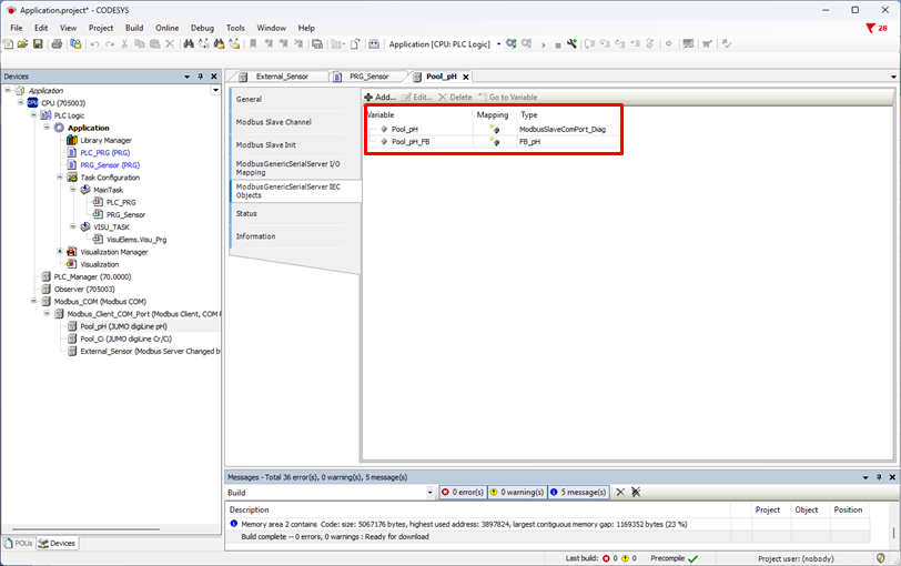
JUMO Modbus devices have two Function_Blocks. One comes from CODESYS and is responsible for Modbus communication. The second comes from JUMO and operates the actual device.
Since an external/your own sensor only has the Function_Block from CODESYS, the following steps must be performed.
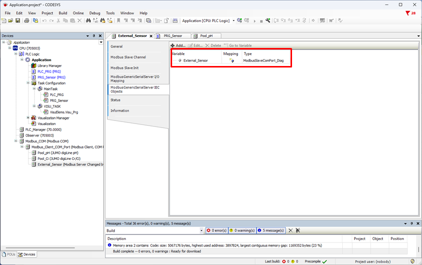
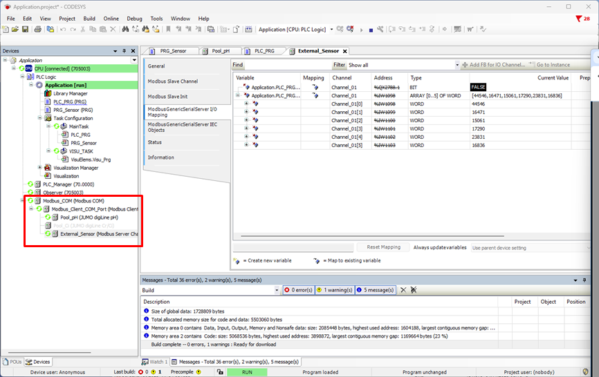
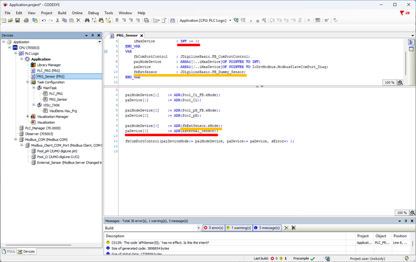
Since three sensors are now connected to the serial interface, the iMaxDevice is set to "3" and the assignments duplicated and modified in the program section. The FB of the External_Sensor (identical name) can be assigned for paDevice[3]. A Dummy Function_Block now has to be used for paiModeDevice[3]. It is already prepared and can be found in the JDigiLineBasic library. Create an instance of this and transfer in the program section.
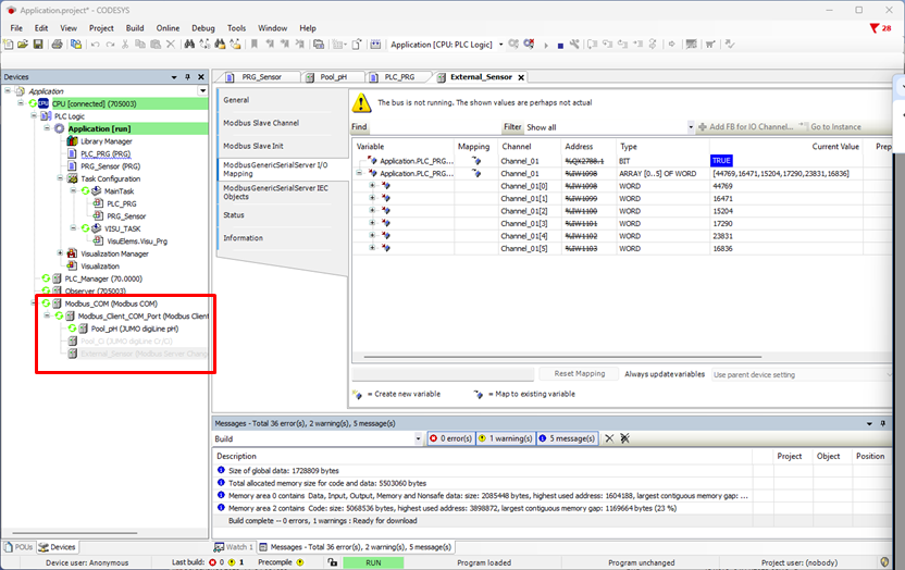
If the "Pool_pH" sensor is put into calibration mode, the communication of the external/your own sensor will now be monitored.
The "Pool_Ci" sensor is first activated in order that it can update its process values.
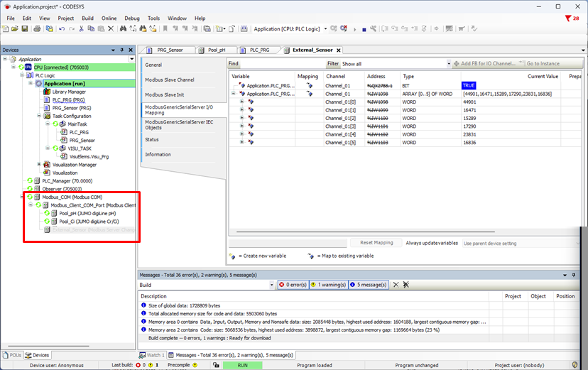
The external/your own sensor will then be activated so that the process values can be updated.