
Signals are used to record the process values, states or counter readings of an application or process. For example, a Signal can represent a temperature value, digital value, text value or counter value.
Virtual signals can also be created. These internal values have the same range of functions as normal signals that are based on a datasource. To create a virtual signal, you only need to create a signal without a datasource, data connection and address. They can be used as auxiliary values for formulas, reports, scripts or animations.
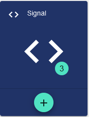
Use the Plus sign to create a new Signal. If you want to edit a Signal, click the button (the area around the Plus sign) to get a list of all existing signals. From there you can select the signal to be processed.
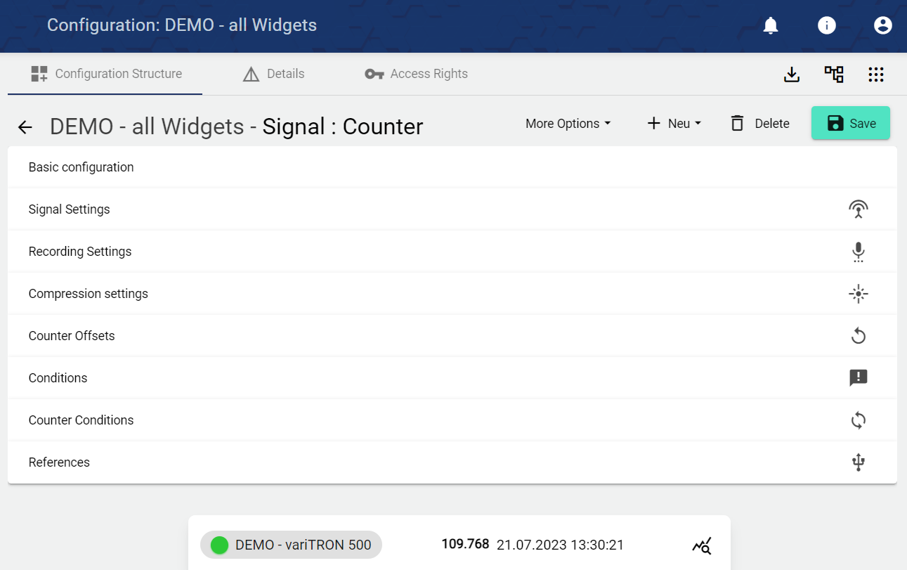
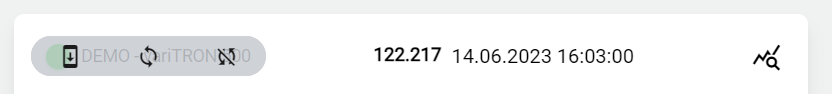
The associated datasource and its status are displayed in each signal. By hovering over the datasource, the configuration can be sent to the device quickly and easily without having to navigate to the "datasource" configuration item.
Basic Configuration
-
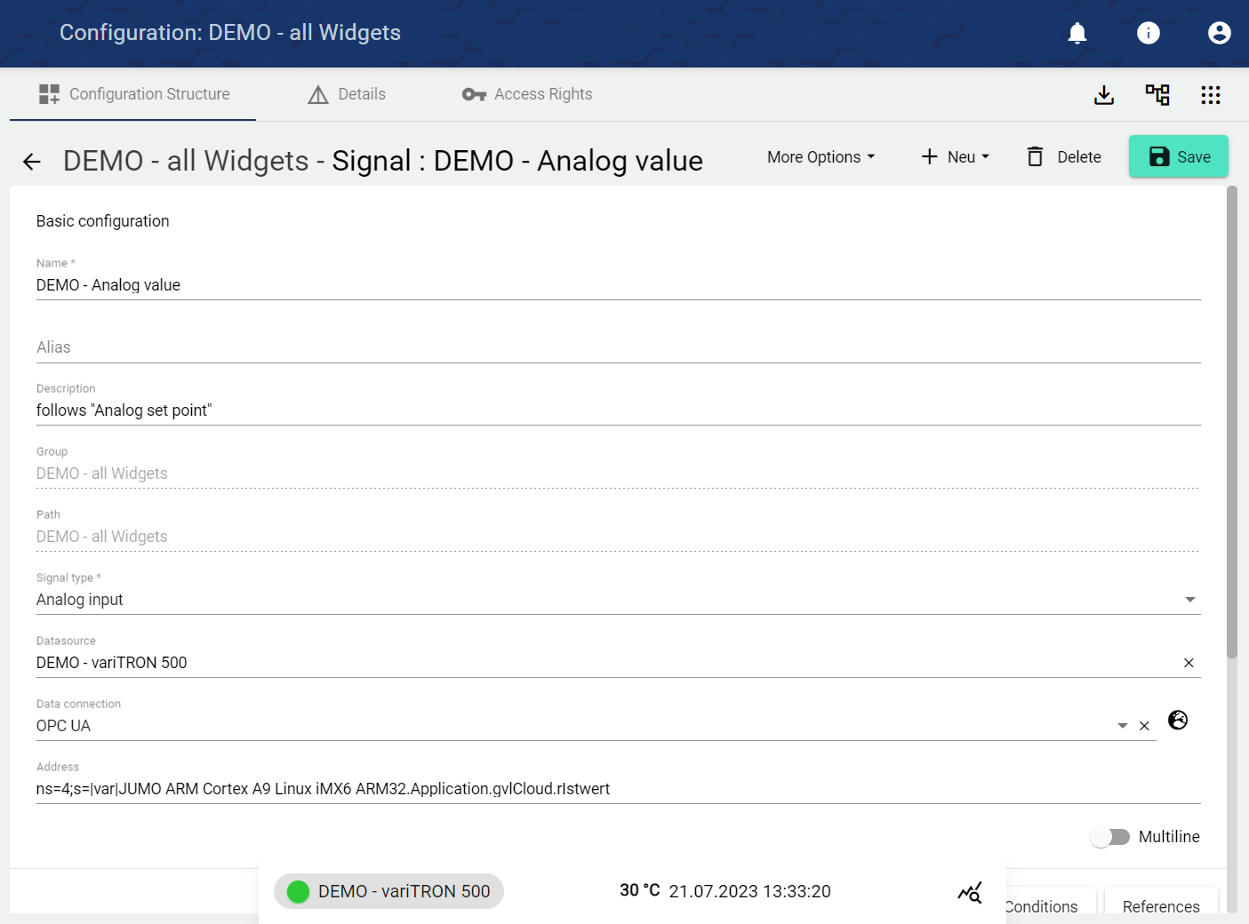
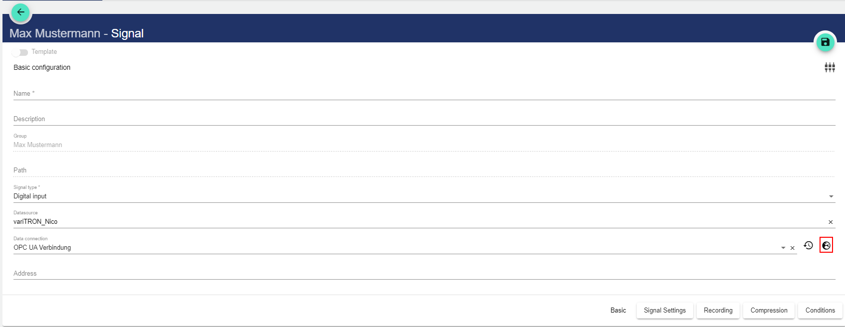
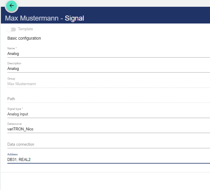
Assign the name of the Signal in the Basic Configuration. The Description field is optional. The "Group" field shows the Group in which this Signal was created. The path is generated automatically by the system.
-
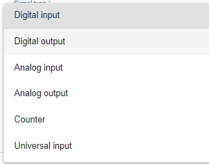
Selecting "Signal type" opens another drop-down menu.
|
Digital input |
Acquires data in digital binary form (On/Off or 1/0) as input |
IoT platform receives IoT device data. |
|---|---|---|
|
Digital output: |
Emits acquired data in digital form (On/Off or 1/0) |
IoT platform sends data to the IoT device. |
|
Analog input |
Acquires data in analog form as input. |
IoT platform receives IoT device data. |
|
Analog output |
Outputs the acquired data in analog form. |
IoT platform sends data to the IoT device. |
|
Counter |
Acquires data as a count value (1, 2, 3, 4, ...). Resetting to 0 is possible. |
The IoT platform receives IoT device data and also sends data to the IoT device. |
|
Universal input |
Acquires general data from your system, e.g. text values |
IoT platform receives IoT device data. |
|
Universal output |
Outputs general data, e.g. text values |
IoT platform sends data to the IoT device. |
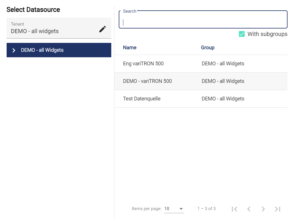
Clicking the "Data Source" field opens another window. A previously created Datasource can be selected there.
Clicking the "Data Connection" field opens another window. A previously created Data connection can be selected there.
Then the address must be entered depending on the data connection. The descriptions for OPC UA, Modbus TCP, PROFINET (S7 TCP) and BACnet are listed below. Further address descriptions of other data connections are available on request.
OpcUa:
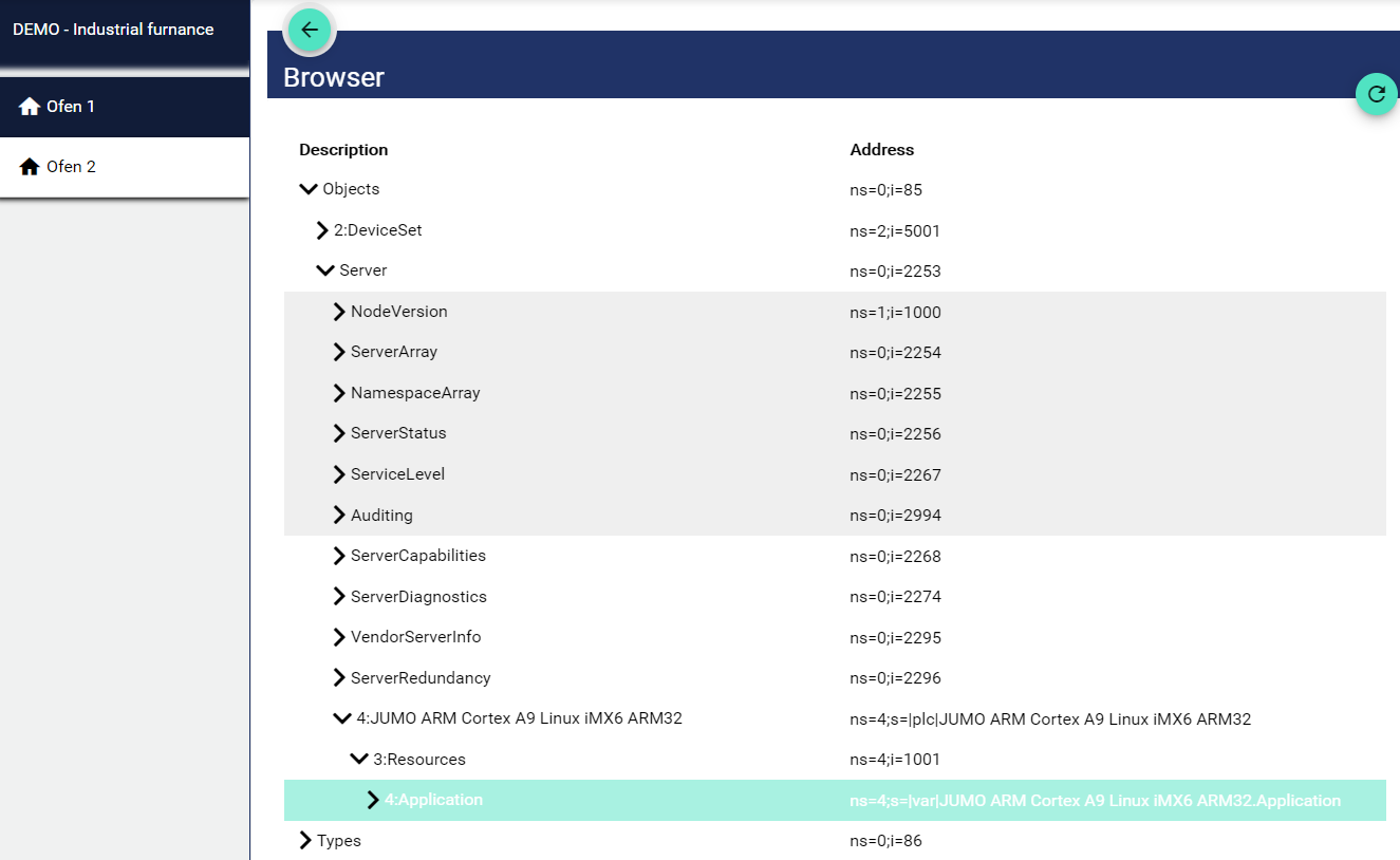
In OpcUa, the "Browse" function can be used to access the addresses within the controller (variTRON) via the "Globe" symbol.
The OPC UA variable can then be selected in the JUMO variTRON via the following path. Depending on the project engineering the value may also be found under "DeviceSet".
Modbus:
In Modbus, the "address" is composed of 40,000 or 30,000, including the digit indexed from 0. This means that if the specified original does not start at 0, it is adjusted accordingly. With a start index of 0, the offset can thus be added directly to 40,000 from the Modbus. With a start index of 1, as here in the table for example, +1 must be added to the offset. It follows that we must start with 40.001:WSREAL. A simpler and equally functional notation would be: 4xdecimalvalue+1:type or in the example: 4x34.817:WSREAL. The 3x addresses are for reading variables; the 4x addresses are for reading and writing variables. In the lower table the data type (e.g. WSREAL) with explanation can be found. This is appended as a conclusion with a colon.
3x-addresses= R/O (Read only) - variable
4x = R/W (Read/Write) - variable (see table)
Here is an aid to conversion: Binary-Decimal-Hexadecimal Converter
Address: "3x decimal value+1 : data type" or "4x decimal value+1 : data type".
|
Examples |
Hex |
Dec |
"Address" of the Cloud and SCADA application |
|---|---|---|---|
|
Analog variable 1 (Modbus frame) |
0x8800 |
34.816 |
4x34817:WSREAL |
|
Analog variable 3 ("direct") |
0x1075 |
4.213 |
4x4214:WSREAL |
|
Digital variable 2 (Modbus frame) |
0x8805 |
34.821 |
4x34822:INT |
|
Digital variable 3 ("direct") |
0x1373 |
4.979 |
4x4980:INT |
|
Integer variable 1 ("direct") |
0x11F2 |
4.594 |
4x4595:INT |
|
External text 1 ("direct", e.g. LS 700)* |
0x1540 |
5.440 |
4x5441:CHAR,244 |
-
The data type for text signals corresponds to: " Char[244] ".
The following data types are currently available with the Modbus driver:
Example: Analog input module 4-fold with slave address = 3 and Modbus address (decimal) = 84
Address: 4x85:WSREALSLAVE3
|
Data type |
Explanation |
|---|
|
Data type |
Explanation |
|---|---|
|
WSREAL |
A 32-bit floating-point number data type with reversed byte order (big-endian),2 registers/word floating-point number. |
|
WSDOUBLE |
A 64-bit floating-point number data type with reversed byte order (big-endian),4 registers/word of floating-point number. |
|
WSDWORD |
A 32-bit unsigned integer data type with reversed byte order (big-endian), 2 registers/word integer unsigned |
|
WSDINT |
A 32-bit signed integer data type with reversed byte order (big-endian), 2 registers/word integer signed |
|
WSQWORD |
A 64-bit unsigned integer data type with reversed byte order (big-endian), 4 registers/word integer unsigned |
|
WSQINT |
A 64-bit signed integer data type with reversed byte order (big-endian), 4 registers/word integer signed |
|
INT |
A 16-bit signed integer data type, 1 register/word integer signed |
|
WORD |
A 16-bit unsigned integer data type, 1 register/word integer signed |
|
X |
A bit data type to represent a digital signal |
|
B |
A bit data type to represent a digital signal |
|
BYTE |
Ein 8-Bit Integer-Datentyp ohne Vorzeichen, unsigned |
|
C |
An 8-bit signed integer data type |
|
CHAR |
An 8-bit signed integer data type |
|
TIMER |
A timer data type for use in timer circuits |
|
COUNTER |
A counter data type for use in counts |
PROFINET (S7 TCP):
Addressing the signal occurs according to the format:<data block number,> <data type><byte offset><.array length>
Here an example:
Example with explanation:
|
DB31, |
REAL |
2 |
|---|---|---|
|
data block number: Database that is accessed |
data type: Data type that is accessed |
byte offset: Data point to be accessed |
|
S7 PLC |
Node-Red |
|---|
|
S7 PLC |
Node-Red |
|---|---|
|
MR30 |
MD30 as REAL |
|
DB10,LR32 |
LREAL by Byte-Offset 32 in DB10, only for S7-1200/1500 |
|
DB10,INT6 |
DB10.DBW6 as INT |
|
DB10,I6 |
DB10.DBW6 as INT |
|
DB10,INT6.2 |
DB10.DBW6 and DB10.DBW8 in a array With the length 2 |
|
PIW30 |
PIW30 as INT |
|
DB10,S20.30 |
String at offset 20 with a length of 30 (actual array length 32 due to the format of the string type, length byte is read/written). |
|
DB10,S20.30.3 |
Array with 3 strings at offset 20, each with a length of 30 (actual array length 32 due to string type format, length byte is read/written). |
|
DB10,C22.30 |
Character array at offset 22 with length 30 (best not to use with strings, because the length byte is ignored) |
DB38,S0.256
data block number: DB38 is the database number;
data type mit byte offset: S0 is for specifying a string with offset 0 in the database;
array length:256 to specify the string is 256 bytes long.
Other examples:
DB10,DT0 - Date and time
DB10,DTZ0 - Date and time in UTC
DB10,DTL0 - DTL in newer PLCs
DB10,DTLZ0 - DTL in newer PLCs in UTC
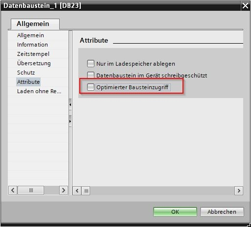
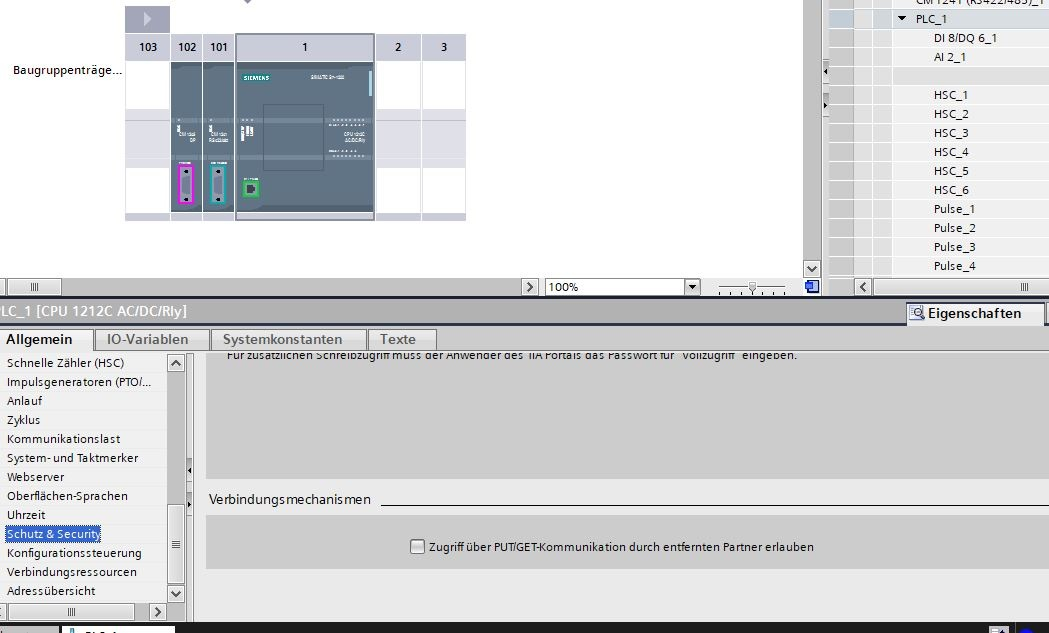
Tip: Settings in S7
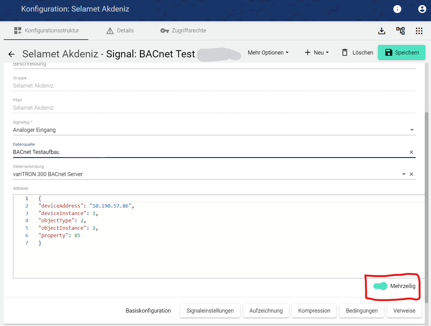
BACnet:
These following lines of code represent a simple JSON format used to communicate with a BACnet device. BACnet stands for Building Automation and Control Networks and is a communication protocol specifically designed for communication between devices in building automation systems.
-
"deviceAddress": This is the IP address of the BACnet device. In this case it is "10.190.57.86".
-
"deviceInstance": This is the instance number of the BACnet device. In BACnet, this corresponds to a unique identifier for a device within a BACnet network. Here the instance number is "1".
-
"objectType": This is the type of the BACnet object. The number "2" corresponds to an analog input object in BACnet.
-
"objectInstance": This is the instance number of the BACnet object. In BACnet, this corresponds to a unique identifier for an object within a device. Here the instance number is "1".
-
"property": This is the property of the BACnet object to be accessed or changed. The number "85" corresponds in BACnet to the "Present Value" property, which represents the current value of the object.
Signal settings
The signal settings depend on the signal type. This item is not available for the universal input / universal output type.
Digital input / output
-
Digital off label is displayed when the signal is off; can be reassigned and a color can be selected.
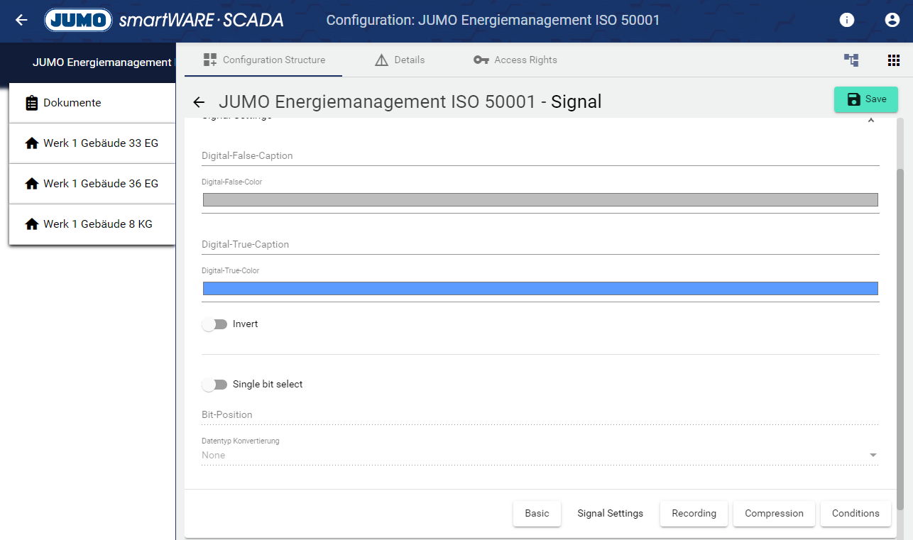
-
Digital on label is displayed when the signal is on; assign and a color can be selected.
-
Activating the "Invert" switch negates or inverts the signal.
-
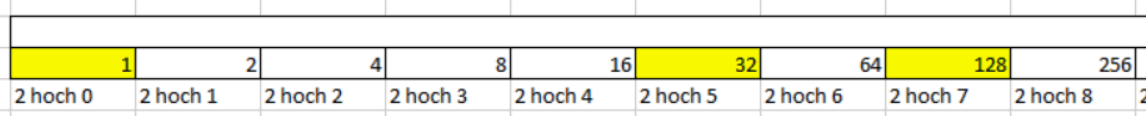
By activating the " Single bit select" switch, a single bit can be analyzed. The advantage of this is that several pieces of information, such as several alarm values, can be read out from just one signal. In the lower field it can be selected into which data type the signal is converted. With an "Integer" e.g. all numbers between 0 and 65.535 can be represented with 16 bits. If the number 161 is transmitted, this means that bit 0, bit 5 and bit 7 are "TRUE", the rest is "FALSE". With the "bit select" one queries so to speak an integer at only one certain bit position, in order to identify thus several conditions or alarms from one signal.
Analog input / output
-
Assign a minimum/maximum value that can be detected by the analog signal input or output from the analog signal output. Values above and below this are also recorded. However, when setting a value make sure not to exceed certain values.
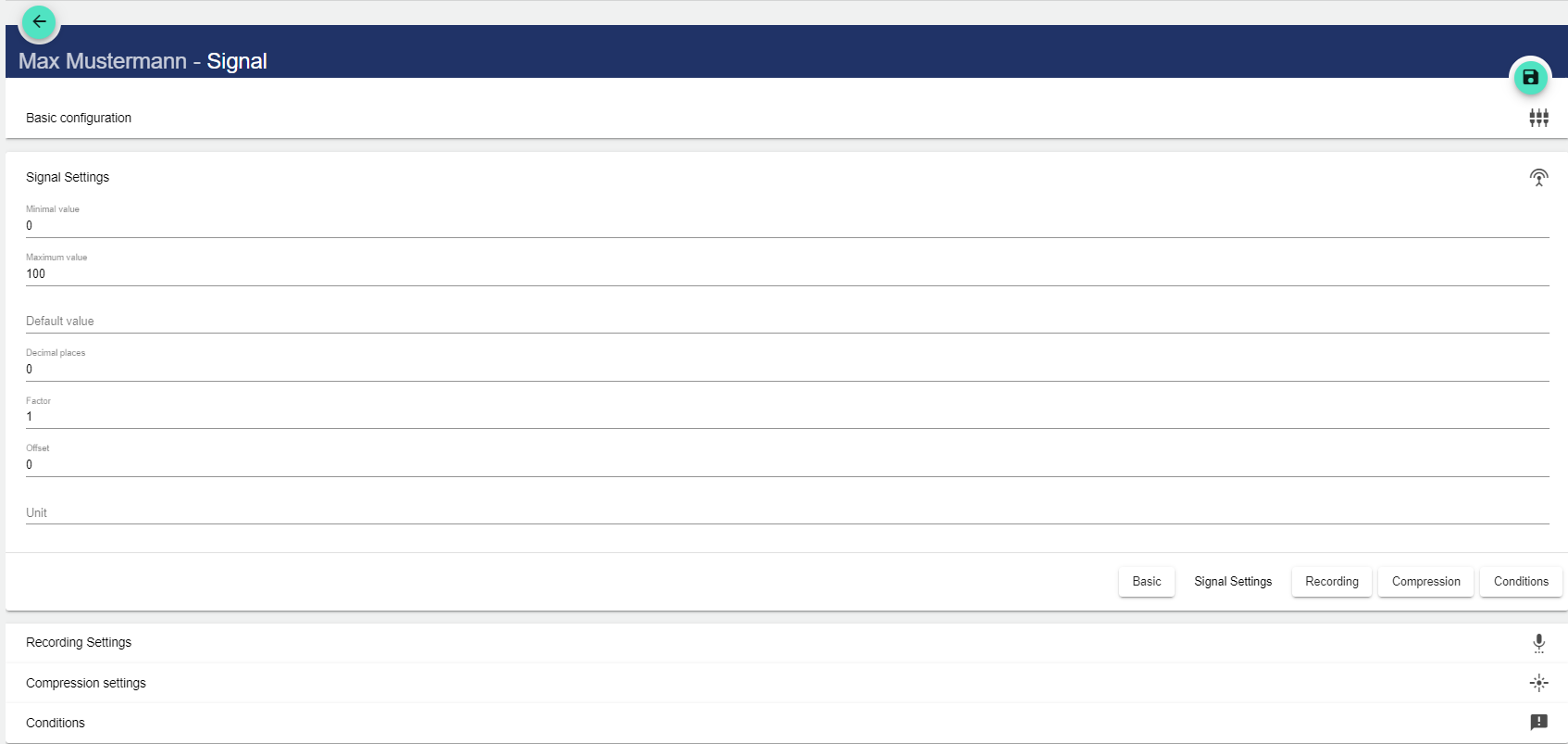
-
Set a default value if no value has been acquired/output yet.
-
By adding decimal places, you can set the precision with which the signal is to output the values of your plant, as these are only used for the display in the system.
-
The factor is multiplied by the original value of the signal.
-
The offset specifies the fixed value by which the original value is shifted in the positive or negative direction (e.g.: value shift +1).
-
The unit is the measured value to be displayed. (e.g.: V or m³/h)
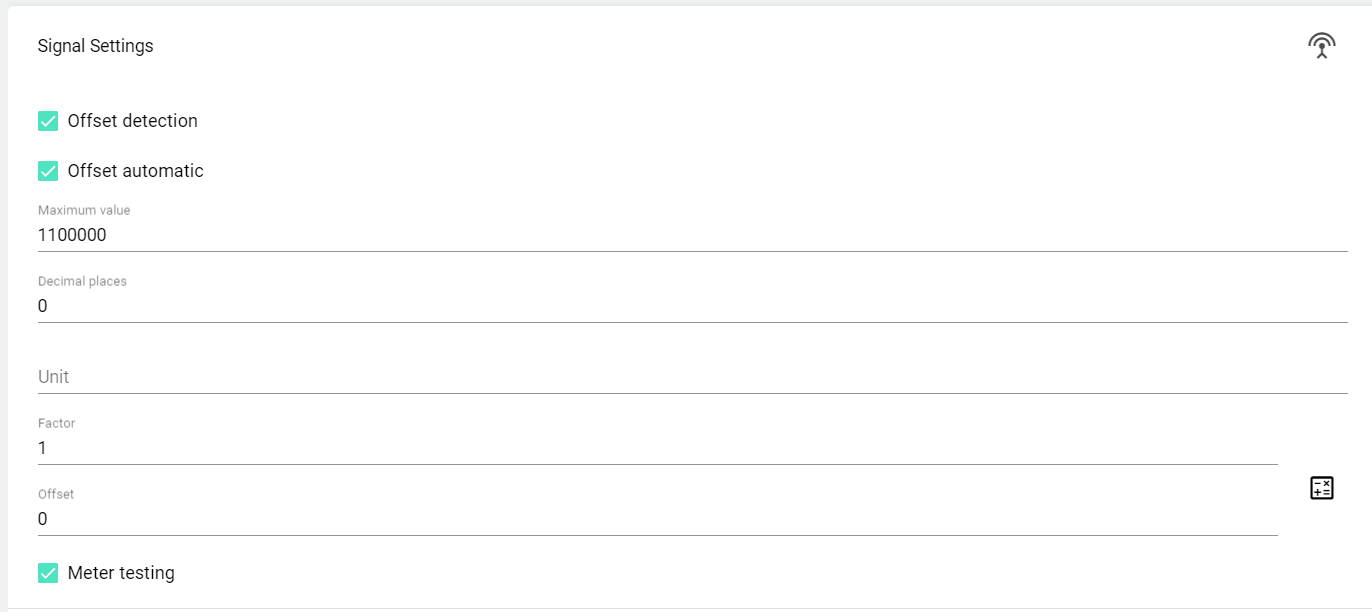
Counter
Output settings
This setting option is only available for analog and digital output signals!
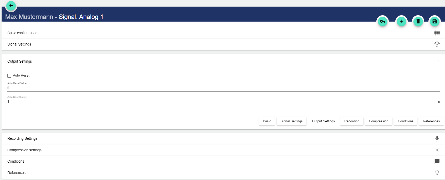
-
In the output settings, a value can be specified to which the signal is set with the "Automatic reset" function, after it has been sent to the IoT device.
-
It is also possible to set a delay (in seconds) for the automatic reset of the output signal.
Recording settings
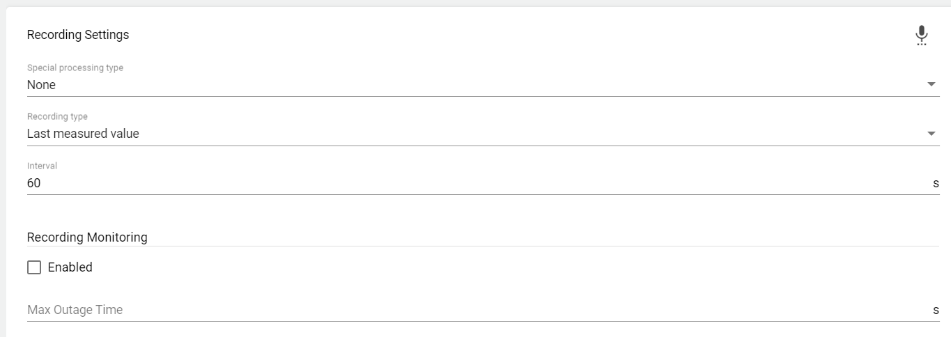
Select special processing type:
-
Select special processing type:
-
None
-
Live flow meter
-
Watchdog: Used to detect failure of the digital system.
-
-
Select recording type:
-
Average value (Is formed in the Edge Gateway or in the JUMO Cloud Gateway from the Live Data)
-
Last measured value (only the last value is recorded, usually useful for fill levels)
-
-
Select the interval at which the last measured or average value is to be queried. The interval is specified in seconds.
Under "Interval", the interval in seconds is specified at which the IoT device (JUMO variTRON) transmits the signal data to the IoT platform.
Compression settings
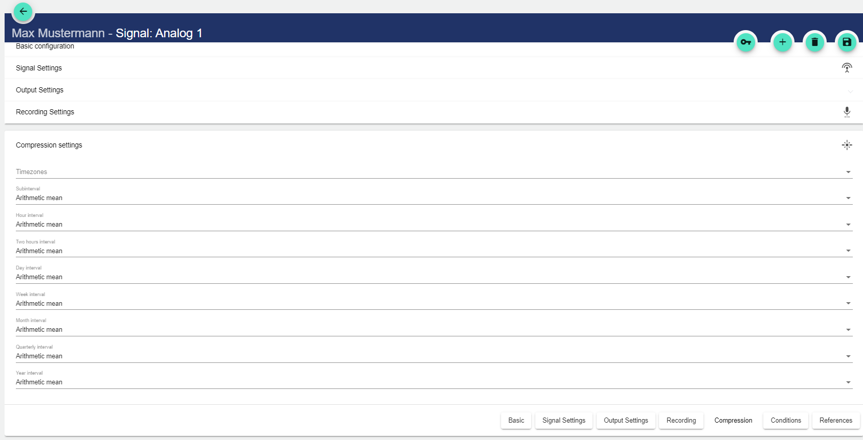
Under Time zones you can set in which time zone the collected data will be stored in the system. If time formats do not fit, a fixed time zone can be selected manually here.
The following interval types are available for selection:
Process Interval refers to the normal transfer rate selected in the Recording Settings area.
|
Interval Type |
Description |
|---|---|
|
Minor interval |
Equivalent to 15 minutes and is therefore the smallest interval. |
|
Hourly interval |
Equivalent to one hour and thus 4 times the minor interval. |
|
Two-hourly interval |
Equivalent to two hours and thus twice the hourly interval. |
|
Daily interval |
Equivalent to 24 hours and thus 12 times the two-hourly interval. |
|
Weekly interval |
Equivalent to 7 days (168 hours) and thus 7 times the daily interval. |
|
Monthly interval |
Equivalent to 30 days (720 hours) / 28 days (672 hours) / 29 days (696 hours) / 31 days (744 hours) and thus approximately 4 times the weekly interval. |
|
Quarterly interval |
Equivalent to 90 days (2160 hours) / 91 days (2184 hours) / 92 days (2208 hours), and thus approximately 3 times the monthly interval. |
|
Yearly interval |
Equivalent to 365 days (8760 hours) / 366 days (8784 hours) and thus 4 times the quarterly interval |
When you fill in the following fields, a drop-down menu opens in each case:
|
Setting |
Description |
|---|---|
|
None |
The value is not recorded. |
|
Weighted average |
The average value is evaluated taking account of the duration of the filling levels or states. |
|
Arithmetic average |
The average value is calculated from the sum of the measured values divided by the number of values. |
|
Difference |
The difference between two selected variables is calculated. |
|
Sum |
Totals all underlying records. |
|
Time |
A time record is generated. |
|
Text |
- |
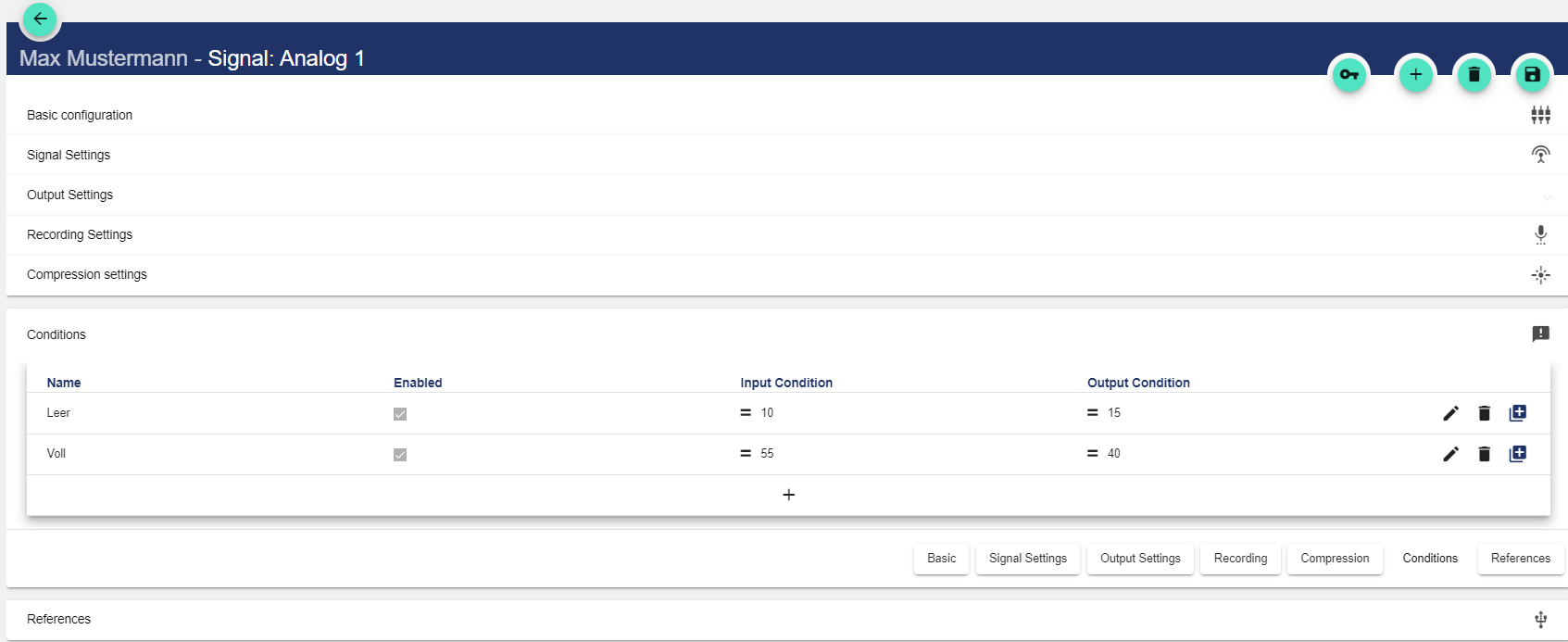
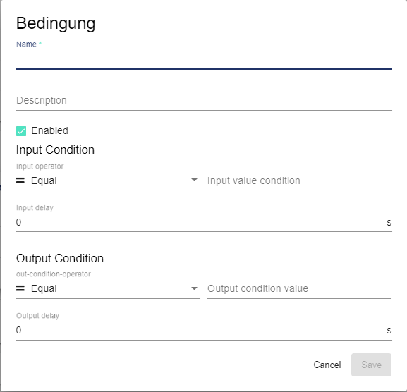
Conditions
Before editing the conditions, the basic configuration must be saved!
Before editing the conditions, the basic configuration must be saved!
-
Assign a name to the condition.
-
Assign an optional description text.
-
If the check mark is set in the "Enabled" field, enable the conditions.
-
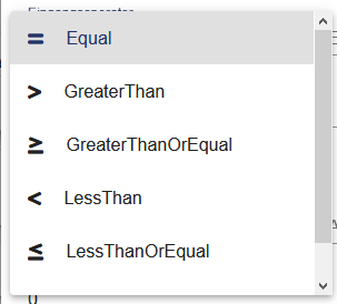
Assign input operator. This serves as a comparison operator and defines the time from which the condition is fulfilled.
-
Assign comparison value 1.
-
The input delay specifies the time in seconds during which the condition must at least be fulfilled.
-
Assign output operator. This serves as a comparison operator and defines the time from which the condition is no longer fulfilled.
-
Assign comparison value 2.
-
The output delay specifies the time in seconds during which the condition must no longer be fulfilled.
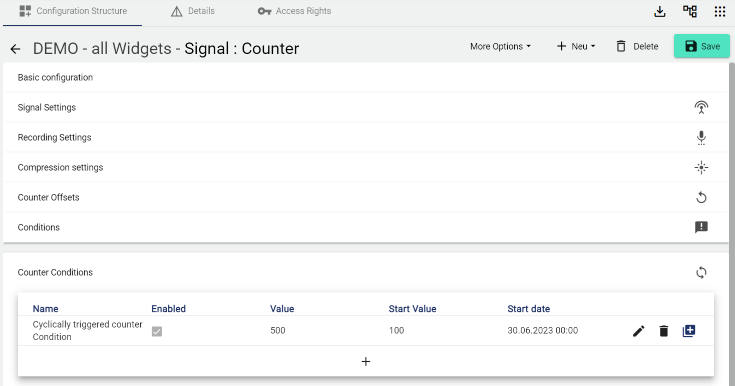
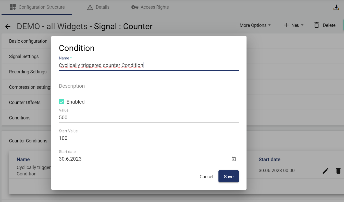
Counter conditions
A counter condition is an optionally adjustable limit value that is triggered cyclically, e.g. every 500 operating hours. The value specifies how long the counter should count until another event is triggered. In our example value=500. The start value corresponds to an offset. By entering a start value, the counter condition can be triggered with a delay when it is run again. E.G.: Start value=100, means that on the next run the counter condition will only be triggered at 600 hours. The start date determines from when the counter is to count.
The counter condition only appears with signal type "Counter".
Before editing the conditions, the basic configuration must be saved!
References
All references of the signal are displayed.
AuditLog
The AuditLog is a change log that transparently shows how the object was changed. For some objects, it also shows which target values were set by a specific person. Power users can use the button on the right-hand side to get a detailed view of exactly what has been changed in the configuration.
The AuditLog can be used to quickly trace what happened to the object last. It corresponds to an extract from the Control Operation Archive.