As from system version 9.1, the controller modules connected to the system bus will be automatically extracted. The associated controller screens will be displayed dynamically in Visu template.
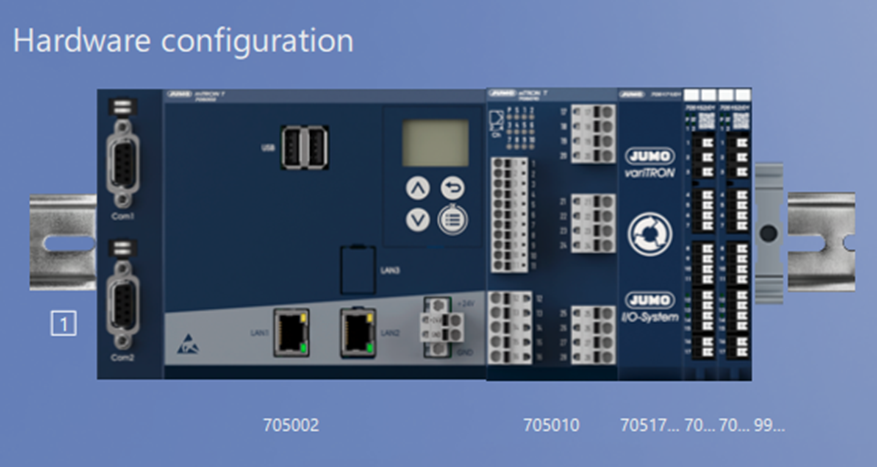
An example is a JUMO variTRON 500 which the following hardware controllers are connected to:
-
1 × hardware controller of type 705010
-
2 × hardware controller of type 705152
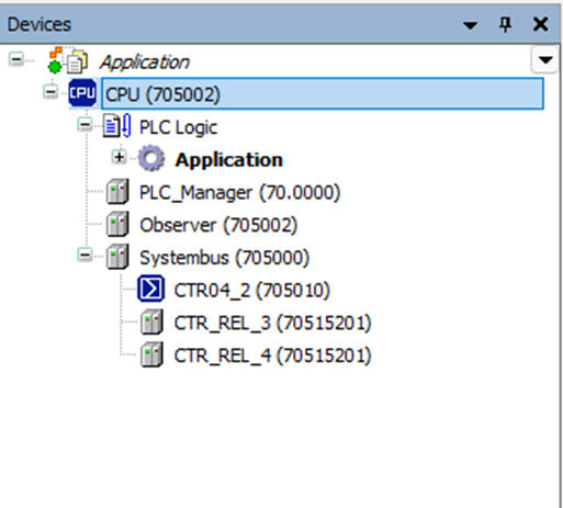
Detection of the modules in CODESYS
After the controller modules are connected, the CODESYS project must be opened. The three connected modules are displayed in the device description. CODESYS can then be closed again. The project is saved in this process.
System start and automatic visualization
After data transfer of the setup to the variTRON system, the system bus is extracted when the system is booted up. The controller screens are automatically generated in this process.
A distinction is made between hardware controllers of the type 7050XX and hardware controllers of the type 7051XX.
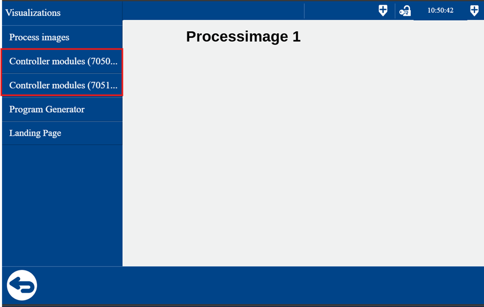
Since two hardware controllers of the type 7051XX are connected in the example, they are shown visually in the second menu item in Visu template.
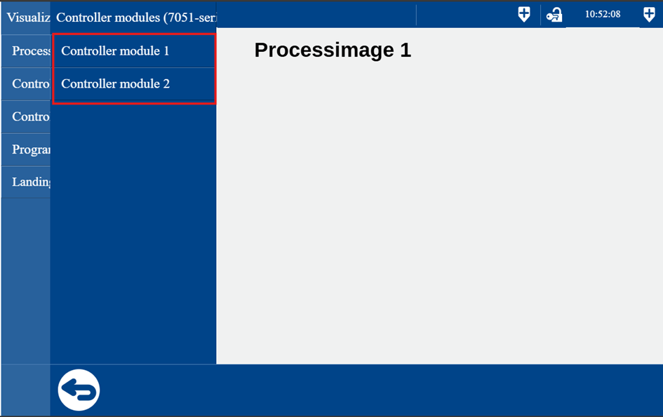
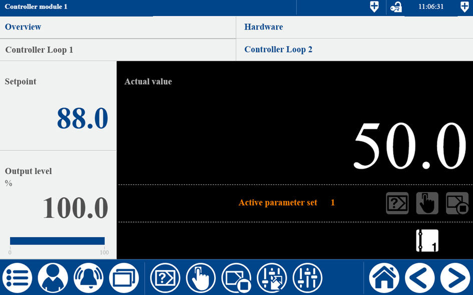
After switching to the first controller module of type 705152, the relevant controller screen is displayed.
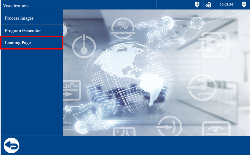
Switch to Landing Page
After configuration, a new menu item Landing Page appears in Visu template in the visualization menu.

The user can switch to the Landing Page by pressing the relevant button.
Return to visualization
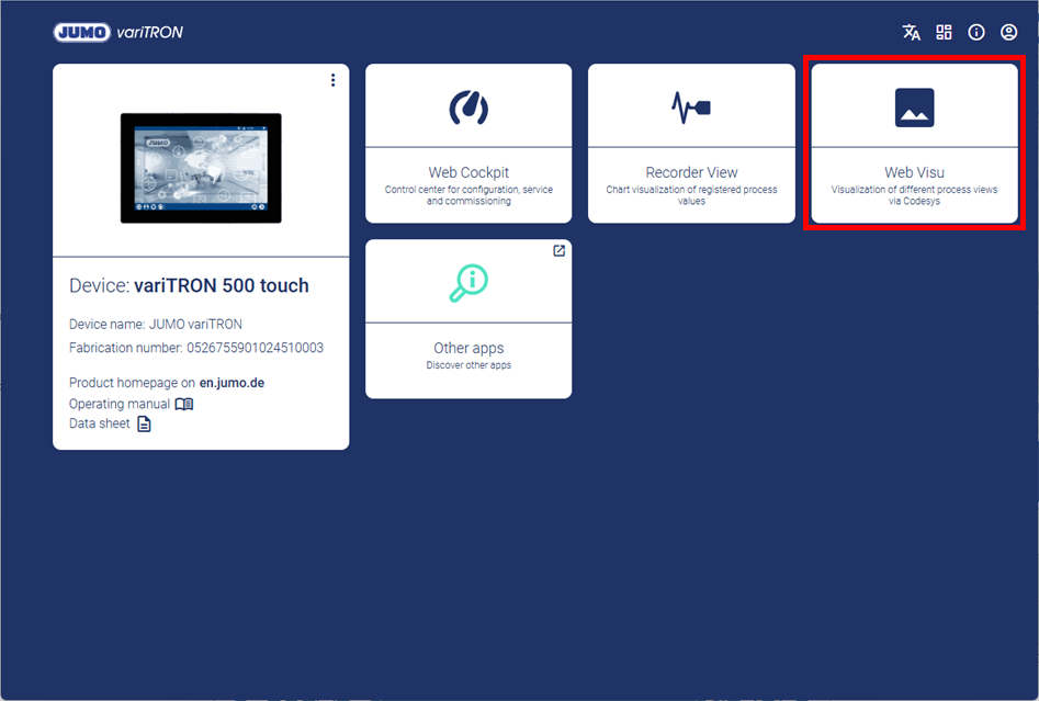
The user switches from the Landing Page back to the visualization by selecting the Web Visu tile.