Configuring the controller
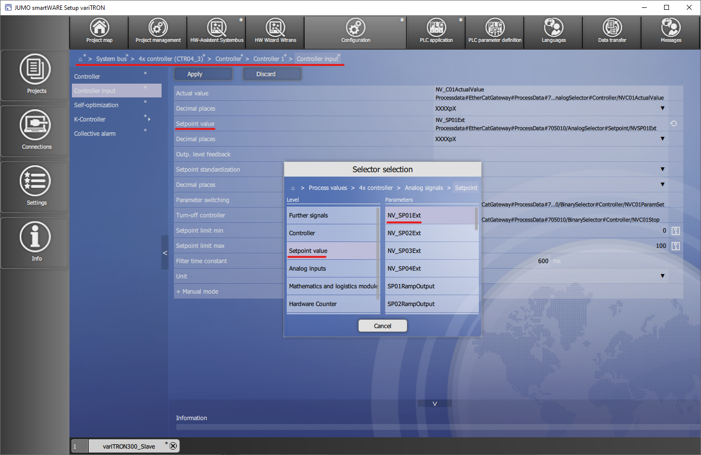
In smartWARE Setup, in the Configuration area under ![]() > System bus > 4x controller (CT04_x) > Controller > Controller 1 > Controller input, the setting for the setpoint specification is made from CODESYS.
> System bus > 4x controller (CT04_x) > Controller > Controller 1 > Controller input, the setting for the setpoint specification is made from CODESYS.
For Setpoint value the selector Setpoint value → NV_SP01Ext must be selected here.
The PLC project is then retrieved.
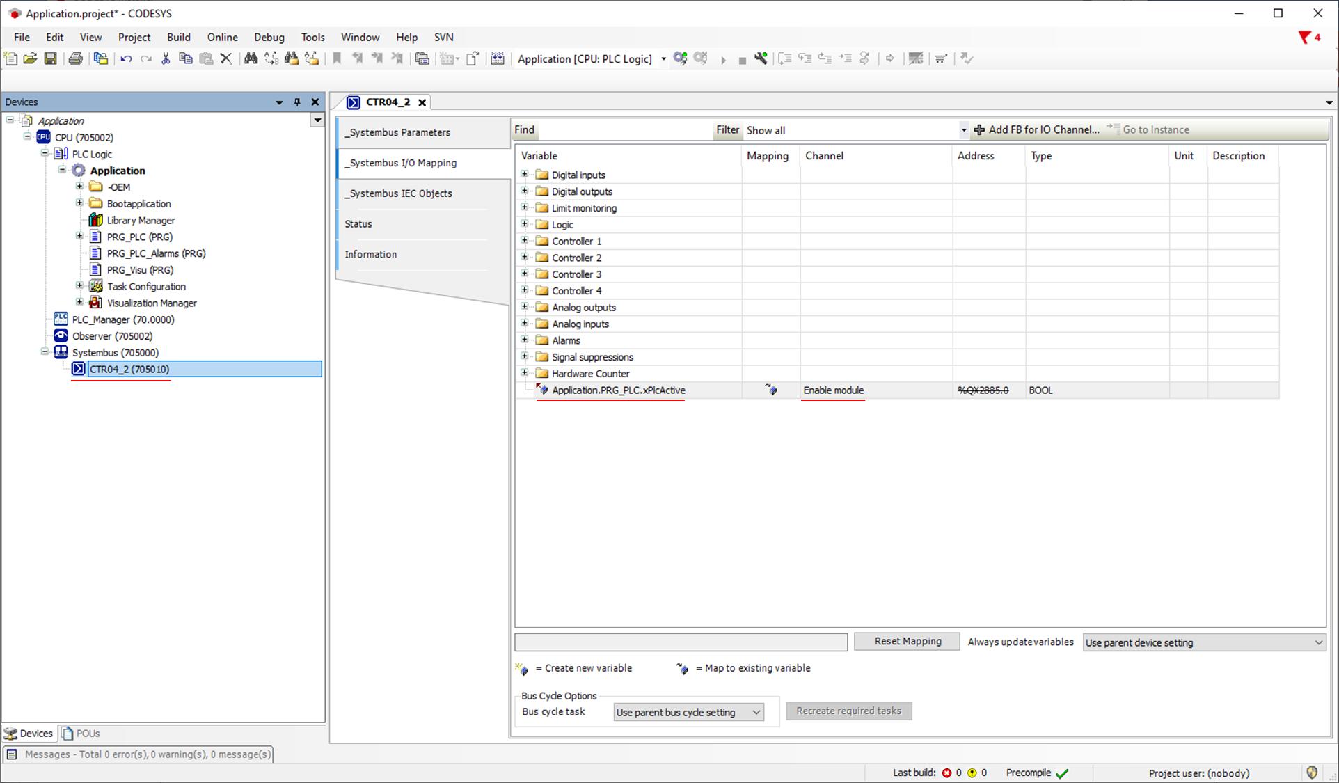
Because the controller needs to be operated via PLC in this case, the corresponding controller module must be activated. For this, the variable Application.PRG_PLC.xPlcActive is entered in the line for the Enable Module channel.
Application.PRG_PLC.xPlcActive
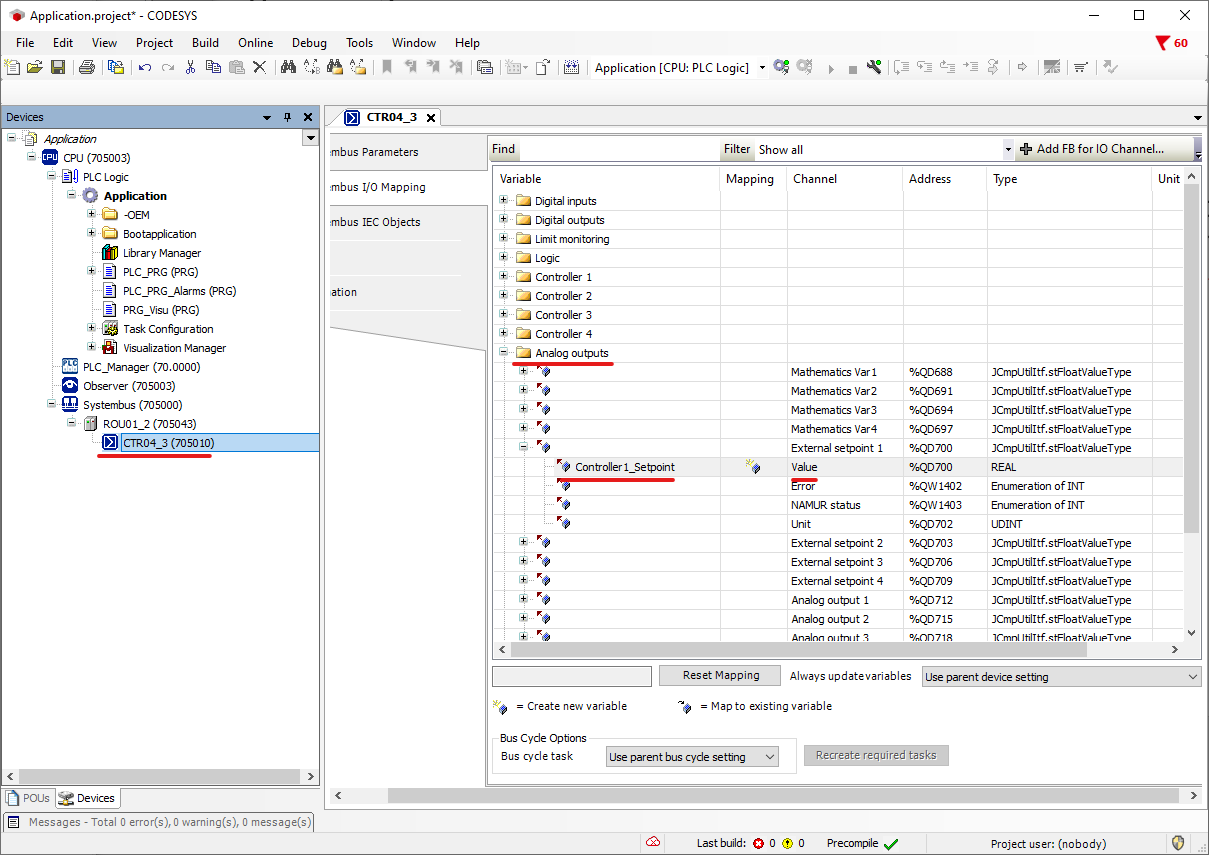
The external setpoint 1, which has already been selected in the JUMO SmartWARE Setup as the controller output, must now be mapped in the PLC. In this example, the variable Controller1_Setpoint is entered in the I/O mapping of the controller under Analog outputs → External setpoint 1 for the Value.