Modbus TCP master
Adding a master interface
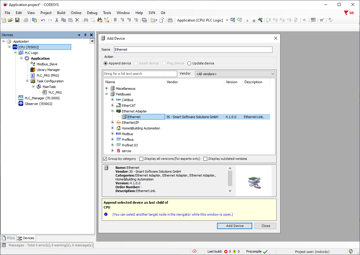
The Ethernet interface must be added to the variTRON that is to be used as a modbus TCP master via the context menu of the CPU and the Add Device... menu item.
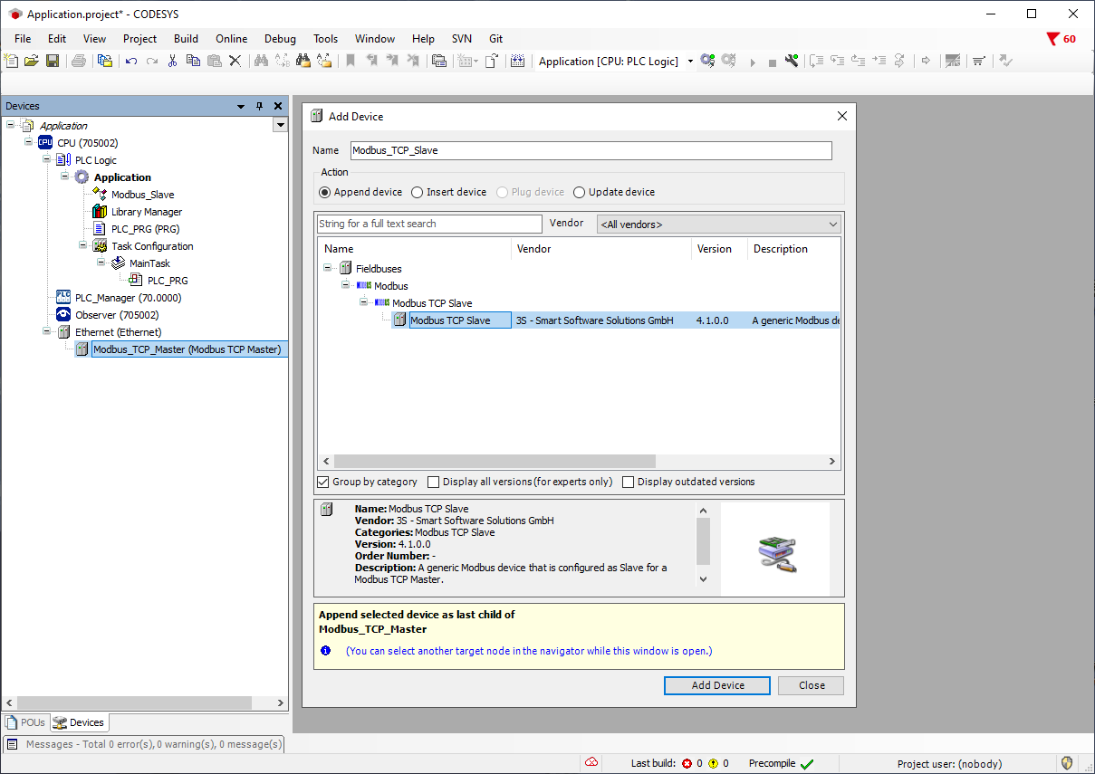
The communication log ModbusTCP Slave Device is then added via the Add Device... menu item in the context menu of the Ethernet devices.

A Modbus TCP slave is now added via the Add Device... menu item in the context menu of the Modbus TCP master so that communication can be established with it.
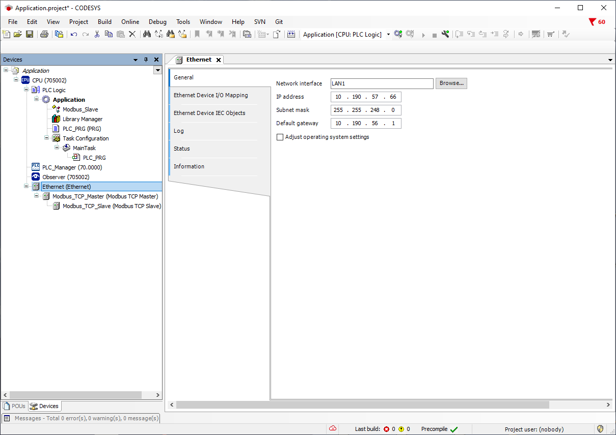
The network interface (LAN port) to be used for communication must be selected on the Ethernet device under General.
Configuring the interface in the modbus TCP master
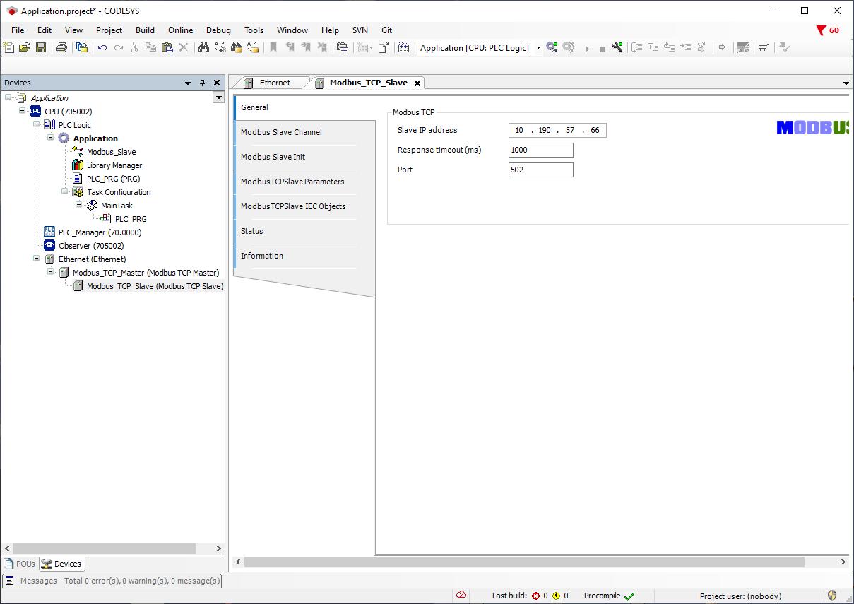
On the Modbus TCP slave under the Modbus TCP master, the IP address of the variTRON to be integrated into the communication as a Modbus TCP slave is entered under General.
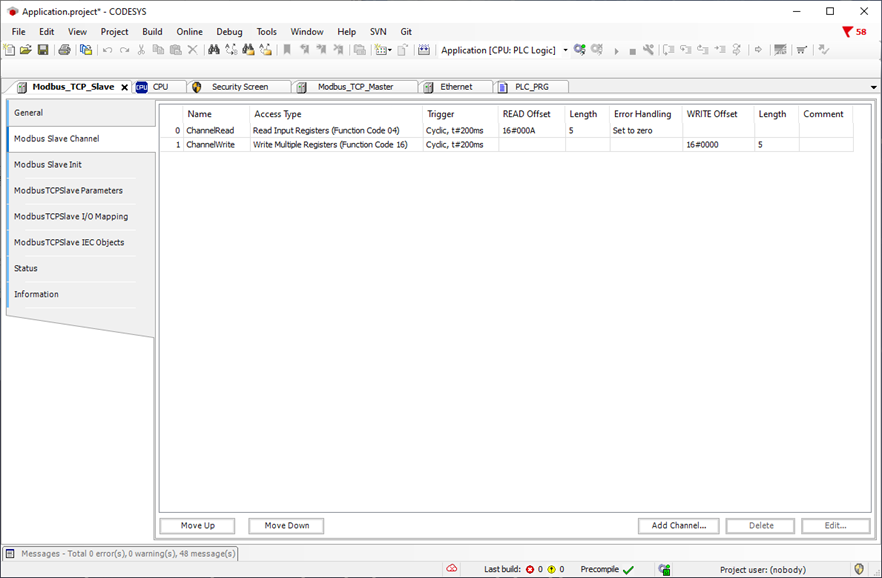
In the Modbus Slave Channel Configuration, channels are created to read and write data areas.
Function code 04 is used to read a data area from the Modbus TCP slave. In this example, the start address from which to read is 10, i.e. 0x000A in hex. Function code 16 is used to write a data area in the Modbus TCP slave. Here the master can write to the slave starting from address 0, i.e. hex 0x0000.
In the ModbusTCPSlave I/O Mapping on the master:
The read range can be recognised by the addresses %IW (Input Word) or by the symbol :IOInput:.
The write range can be recognised by the addresses %QW (Output Word) or by the symbol :IOInput:.
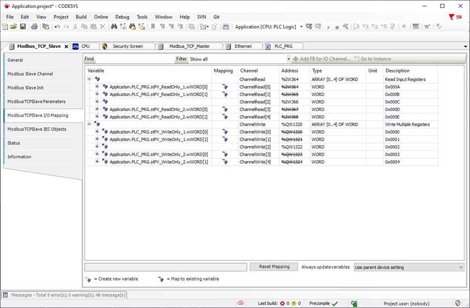
Here too, the required variables must be declared in the ModbusTCP slave I/O mapping or mapped to variables in the application.
Using the structure variable stPV_ReadOnly, the master reads values from the slave.
Using the structure variable stPV_WriteOnly, the master writes values into the slave.